Marshal QR Code: Project Overview
A Physical QR Code Built on a Go Board
Project Overview
This project is a cross-disciplinary endeavor to showcase my proficiency in design, computing, and solving complex problems. I created a custom 25x25 matrix board using a CNC router, then implemented the QR code using encoding algorithms from scratch gaining an understanding of how data is represented in the matrix.
Once I had a grasp on the theory behind the data encoding process using Python, I created a functional QR code that can be scanned with any smartphone or QR code scanner. This physical-digital fusion piece demonstrates the QR encoding process via a Next.js component that references data created by a function that mirrors the phases of the encoding process and seeds that data to Neon. The function operates around the data and EC keywords that are necessary for Reed-Solomon error correction.
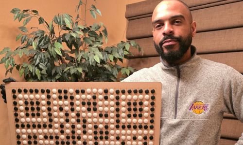
Marshal with the physical Go board QR code
Why We Design
I believe that at the heart of design is creating for people first. Building with unselfish intent produces the best designs. This project is a testament to that philosophy, using the QR code as a symbol of this idea.
The Objective
Create a physical representation of a QR code built on a custom-made go board. The board required is 27"x27" to provide a border for the "quiet zone" and thus was built using a CNC router. The QR code required is a version 2 code, which means it is 25x25 modules. The QR code encodes the URL "http://squaloo.com/marshal-qrcode" using byte encoding with a medium error correction level.
The Process
The process of creating this QR code was a journey of learning and discovery. I started by learning about the basics of QR codes and how they work. I then used Python to generate the QR code data sequence and error correction codewords. Next, I designed the physical board and had it made by Mahesh, a local business owner with a CNC router. Finally, I encoded the data onto the board using black and white go pieces with the help of visualizations from a Next.js component that uses Drizzle and Neon to house data.
Timeline:
Inspiration
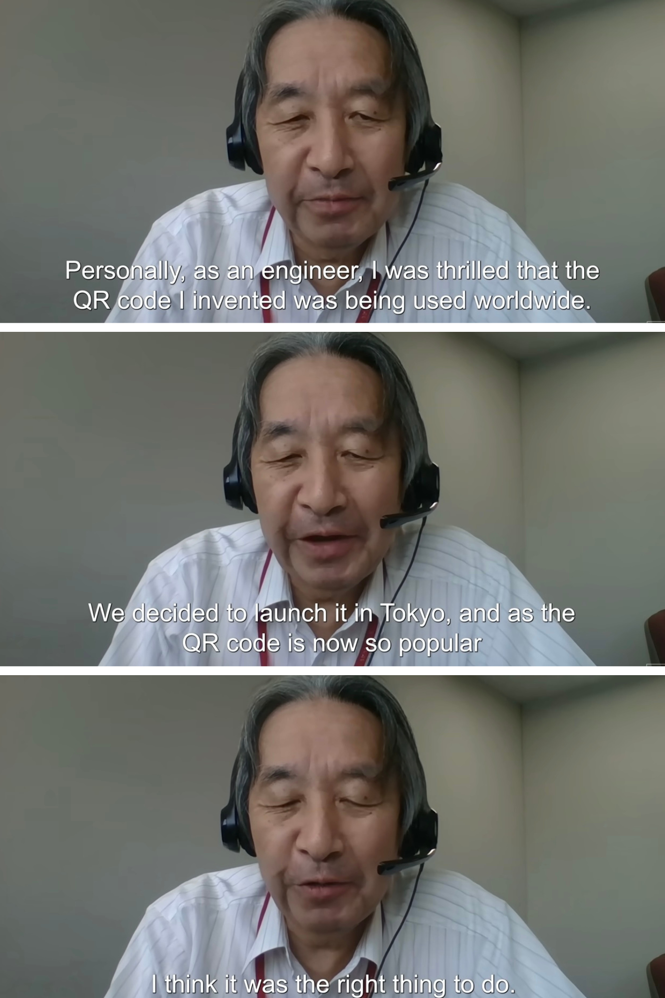
Watching the Veritasium video featuring Masahiro Hara, the inventor of the QR code. A video discussing the creation of the QR code, the inventor himself and his philosophy inspired my project.
Veritasium video on the QR code and its inventor
The Why
I was inspired to create this project after watching a video by Veritasium featuring Masahiro Hara, the inventor of the QR code. In the video, Hara mentions that he did not leverage the patent for the QR code, which allowed it to be proliferated. This resonated with me because of the impact his design has had as a result of that decision.
The QR code represents a perfect blend of utility and design, solving a real problem while being accessible to everyone. This philosophy of creating with unselfish intent is at the heart of my approach to design and technology.
The Outcome
This project was a challenging but rewarding experience. I learned a lot about QR codes, computer science, and the design process. I also had the opportunity to collaborate with a local business owner and learn about CNC routing. Most importantly, I created a project and piece that reflects my design philosophy and my passion for learning.
The Next Steps
I plan to continue to expand on my current work with the QR component and DB set up to make this an interactive lesson to engage w/ computing concepts making the creation of a physical board optional. As well as create more projects that combine physical and digital elements. I'm also excited to share my learnings with others and inspire them to create their own projects.
Interactive QR Encoding Process
Key to undesrstanding the QR code is visualizing the phases data is encoded. To help myself in the physical implementation, I created this component that uses a Typescript function to seed a DB with the specific data from my URL. Navigate through the different phases of QR code encoding to see how the matrix is built up layer by layer. Each phase represents a specific step in the encoding process.
The QR Encoding Process
1. Finder Patterns
QR codes start with three finder patterns in the corners. These distinctive square patterns help QR readers locate and orient the code correctly. Each finder pattern consists of a 7×7 module with a 3×3 black square inside a 5×5 white square inside a 7×7 black square.
2. Separators
Separators are one-module wide white strips that surround the finder patterns. They help distinguish the finder patterns from the rest of the QR code, making it easier for scanners to identify the positioning markers without interference from adjacent modules.
3. Alignment Patterns
Alignment patterns help QR readers maintain orientation, especially for larger codes or when the code is distorted. For a version 2 QR code (25×25), there's one alignment pattern located at position (18,18), consisting of a 5×5 module with a single black module in the center.
4. Timing Patterns
Timing patterns are alternating black and white modules that run horizontally and vertically between the finder patterns. They help the QR reader determine the positioning of each cell in the code, especially when the QR code is distorted or at an angle.
5. Dark Module
The dark module is a single black module that is always placed at the coordinates (8, 4×version+9). For a version 2 QR code, this is position (8, 17). This module is always black and serves as a fixed reference point for the QR code reader.
6. Mode & Character Count
The mode indicator (4 bits) specifies how the data is encoded (numeric, alphanumeric, byte, or kanji). The character count indicator (8 bits for version 2) tells the reader how many characters are encoded in the QR code, helping it properly parse the data.
7. Data Encoding
The actual data is encoded into the QR code following a specific zigzag pattern, starting from the bottom-right corner. The data is first converted to a bit stream according to the encoding mode, with each character represented by a specific bit sequence.
8. Error Correction
Reed-Solomon error correction codes are added to ensure the QR code can be read even if parts are damaged or obscured. The level of error correction (L, M, Q, H) determines how much of the QR code can be damaged while still being readable.
9. Remainder Padding
If there's remaining space in the QR code after the data and error correction bits, padding bits are added to fill the space. These follow specific patterns (11101100 and 00010001 alternating) to ensure the QR code has a balanced distribution of black and white modules.
10. Masking
A mask pattern is applied to ensure there aren't too many adjacent same-colored cells, which could confuse QR readers. Eight different mask patterns are evaluated, and the one that produces the best result according to specific penalty rules is chosen.
11. Format Information
Format information is encoded near the finder patterns and contains data about the error correction level and mask pattern used in the QR code. This 15-bit sequence is protected by its own error correction and is placed in two locations for redundancy.
Challenges and Learnings
Implementing a QR code from scratch presented several challenges:
- Understanding the complex QR code specification and encoding rules
- Correctly implementing the Reed-Solomon error correction algorithm
- Ensuring proper placement of the dark module and format information in code for virtual display of bit encoding process
- Testing different mask patterns to find the optimal one
- Translating the digital implementation to a physical board with precise measurements
Through this project, I gained a deep understanding of how QR codes and computing work at a fundamental level. I learned about binary encoding, error correction algorithms, and the importance of visual patterns in machine-readable codes. The physical implementation added an extra dimension to the learning experience, requiring precision in both the digital algorithm and the physical construction. It also was critical as a visual reference when writing and revising code for the QR code component.
Learn More
Interested in learning more about QR codes or seeing the code behind this project? Check out these resources:
QR Code Component
See the interactive QR code component and explore the code behind it.
QR Code Tutorial
A comprehensive tutorial on how QR codes work and how to generate them.
QR Code Generator Library
An open-source QR code generator library with implementations in multiple languages.
Veritasium QR Code Video
The video that inspired this project, featuring the inventor of the QR code.